whatsapp:+86 13622680352



Screw Jack System for Metal Stamping Equipment
A Screw Jack System for Metal Stamping helps heavy metal-forming equipment adjust large frames, tooling structures, working heights, and other moving sections with stable and repeatable motion.
Metal stamping machines often work with heavy structures and repeated production cycles. Therefore, their adjustment systems must handle high static loads, starting resistance, uneven load distribution, and strict alignment requirements.
In one of our previous metal stamping equipment projects, the lifting system faced three main problems:
- Uneven movement between lifting points
- High starting torque from the heavy structure
- Poor position repeatability after repeated adjustment
Instead of replacing only one component, the project required us to review the motor, gear reducer, screw jacks, guide structure, and synchronization method as one complete transmission system.
Why Metal Stamping Equipment Needs a Screw Jack System
Large stamping machines may need mechanical adjustment for:
- Upper frame positioning
- Tooling height adjustment
- Die setup
- Working table adjustment
- Equipment leveling
- Maintenance positioning
- Process changeover
For a small structure, one lifting point may work. However, a wide and heavy frame often needs several lifting points.
If these points do not move together, the machine structure may tilt.
As a result, engineers may see:
- Die alignment errors
- Uneven mechanical stress
- Higher guide wear
- Increased vibration
- Poor repeatability
- Difficult maintenance adjustment
Therefore, multi-point synchronization becomes an important part of the design.
Project Problem 1: Uneven Lifting Between Screw Jacks
The first challenge in this stamping project was uneven movement.
The structure used several lifting points. However, the real load did not distribute evenly across every screw jack.
This is common in heavy machinery.
The center of gravity, tooling position, frame stiffness, and installation tolerance can all change the load at each lifting point.
If engineers simply divide the total weight by the number of screw jacks, they may underestimate the actual load on one point.
How We Improved the Lifting System
The design review focused on:
- Actual load at each lifting point
- Center of gravity
- Uneven-load factor
- Safety factor
- Frame stiffness
- Guide structure
- Mechanical synchronization
We also matched the screw jack capacity to the most heavily loaded point rather than relying only on the average load.
This approach helps the machine maintain a more level position during adjustment.
For more detailed sizing logic, see How to Size a Multi-Point Screw Jack Lifting System.
Project Problem 2: High Starting Torque
The second problem appeared during startup.
A large stamping-machine structure has significant weight and inertia. In addition, guide friction and mechanical preload can increase the torque needed when movement begins.
The original transmission design did not provide enough margin for these conditions.
As a result, the system could experience:
- Slow startup
- Motor overload
- Higher current
- Mechanical vibration
- Stress on couplings and shafts
How the Gear Reducer Helped
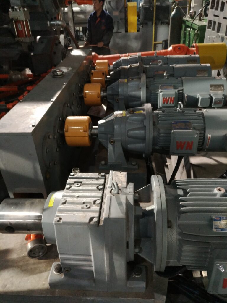
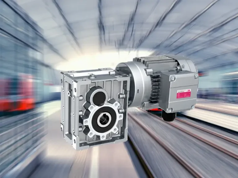
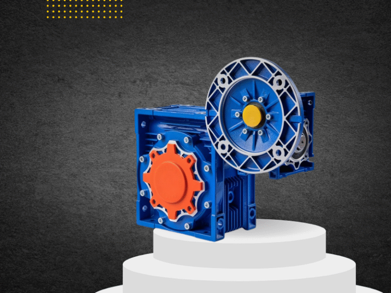
The gear reducer reduces motor speed and increases available output torque.
However, selecting a reducer only by nominal motor power is not enough.
For stamping equipment, engineers should also check:
- Starting torque
- Maximum static load
- Gear ratio
- Service factor
- Motor power
- Acceleration time
- Operating frequency
- Transmission efficiency
In this project, matching the reducer and motor to the real starting load created smoother movement and reduced unnecessary mechanical shock.
Project Problem 3: Position Repeatability
Metal stamping equipment often requires repeated adjustment during die change, setup, or maintenance.
After each adjustment, the structure may need to return to the same working position.
If the lifting system develops too much backlash or synchronization error, the final position can change.
That creates problems for:
- Die alignment
- Tooling setup
- Guide accuracy
- Process repeatability
How We Improved Position Stability
The solution focused on the complete mechanical chain:
- Screw jack backlash
- Gear reducer backlash
- Shaft connection
- Coupling condition
- Guide stiffness
- Limit switches
- Motor braking
- Position feedback where required
For applications that need higher accuracy, engineers can also add encoders or other position sensors.
However, the mechanical structure must remain stable first. A control system cannot fully correct poor alignment or weak frame support.
Gear Reducer Function in Metal Stamping Equipment
A gear reducer has three main jobs in this type of lifting system.
Reduce Speed
Heavy machine structures should move slowly during adjustment.
Slow movement helps operators control position and reduces impact at the end of travel.
Increase Torque
The reducer multiplies motor torque, allowing the system to move heavy structures with a smaller and more practical motor.
Improve Motion Stability
A suitable reduction ratio helps the system start, move, and stop more smoothly.
Therefore, the reducer supports both lifting performance and positioning quality.
What Does the Screw Jack Do in a Stamping Machine?
A screw jack converts rotary motion into linear motion.
In metal stamping equipment, engineers may use it for:
- Vertical adjustment
- Frame lifting
- Die height positioning
- Tooling setup
- Machine leveling
Machine-screw jacks also provide strong mechanical support at low speed.
However, engineers must understand one important point:
The screw jack should not automatically become the main structure that absorbs the full stamping impact load.
In most designs, the press frame, slide, ram, columns, or dedicated press mechanism should carry the main forming force.
The screw jack mainly handles adjustment and positioning unless engineers specifically design and verify it for direct process loading.
This separation protects the lifting system from unnecessary shock and improves service life.
Shock Load: A Major Issue in Metal Stamping Equipment
Stamping machines generate repeated impact and vibration.
Even if the screw jack does not directly carry the stamping force, vibration can still travel through the machine structure.
Over time, this may cause:
- Loose bolts
- Coupling wear
- Gear damage
- Bearing wear
- Backlash growth
- Alignment changes
How to Reduce Shock Problems
Engineers should consider:
- Higher service factor
- Strong mounting bases
- Proper guide structures
- Flexible or suitable couplings
- Controlled acceleration and deceleration
- Regular bolt inspection
The machine frame should also separate process impact loads from precision adjustment components whenever possible.
Side Load on Screw Jacks
Another common mistake is allowing the screw jack to act as both a lifting device and a guide.
Screw jacks mainly work with axial forces.
If the upper structure moves sideways, bends, or twists, the screw may experience side load.
This can lead to:
- High friction
- Screw wear
- Nut wear
- Noise
- Poor positioning
- Reduced service life
Better Design Direction
Use dedicated guides to control lateral movement.
These may include:
- Guide columns
- Linear guides
- Machine slides
- Structural guide surfaces
Then the screw jack can focus on lifting and positioning.
This design usually provides better reliability than asking the screw itself to control machine alignment.
How to Select Screw Jacks for Metal Stamping Equipment
Before selecting a model, engineers should collect several key parameters.
Load
Check the real maximum load at each lifting point.
Also consider uneven distribution and safety margin.
Stroke
Confirm the required adjustment distance.
For long compression strokes, check screw buckling.
Lifting Speed
Stamping-machine adjustment usually does not require high speed.
Therefore, stable low-speed movement often gives better control.
Duty Cycle
Confirm how often operators adjust the machine.
A die-height adjustment system that moves occasionally has very different thermal requirements from an automated mechanism that moves every production cycle.
Starting Torque
Check motor and reducer capacity under startup conditions, not only steady running conditions.
Accuracy
Define the required positioning and repeatability before selecting screw type, gear ratio, and feedback devices.
A more detailed selection workflow is available in Screw Jack Selection Guide.
Safety in Metal Stamping Lifting Systems
Metal stamping equipment combines high force with moving machine parts. Therefore, safety must remain part of the mechanical design.
Important considerations include:
- Upper and lower travel limits
- Emergency stop
- Motor brake
- Mechanical stops
- Overload protection
- Guards around rotating shafts
- Lockout procedures during maintenance
- Secondary holding systems where required
For general machine risk assessment, designers can refer to ISO 12100 Safety of Machinery.
Mechanical power presses also require careful point-of-operation guarding and hazardous-energy control. OSHA provides specific guidance for mechanical power press safeguarding and maintenance.
Why the Complete Transmission System Matters
One lesson from this stamping project was simple:
Changing only the screw jack would not solve every problem.
The real performance depends on the complete chain:
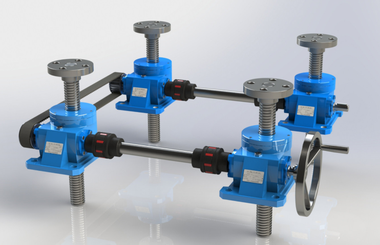
Motor → Gear Reducer → Coupling/Shaft → Screw Jack → Guide Structure → Machine Frame
If one part has the wrong size, poor alignment, or insufficient stiffness, the complete system can lose accuracy.
Therefore, engineers should review the lifting system as one mechanism rather than several independent products.
This approach helps improve:
- Synchronization
- Starting performance
- Position repeatability
- Mechanical life
- Maintenance reliability
Related Applications
The same design principles apply to:
- Press frame adjustment
- Die height adjustment
- Metal forming machines
- Roll forming equipment
- Heavy tooling platforms
- Mold positioning systems
- Sheet metal processing lines
- Industrial press maintenance systems
For related gearbox and drive topics, see NUODUN Gear Reducer and Transmission Products.
Conclusion
A Screw Jack System for Metal Stamping must handle more than machine weight.
It needs to manage uneven load distribution, high starting torque, synchronization, positioning accuracy, vibration, and long-term mechanical wear.
In our project, the key was not simply choosing a larger screw jack. Instead, we reviewed the motor, gear reducer, lifting points, guide system, and frame together.
The result was a more stable lifting concept with better synchronization and more reliable positioning.
For heavy metal stamping equipment, good transmission design starts with one question:
What load should each component really carry?
Once engineers separate lifting loads, guiding forces, and stamping impact correctly, the complete machine becomes easier to control, maintain, and protect.