whatsapp:+86 13622680352



Screw Jack System for Metal Slitting Machine
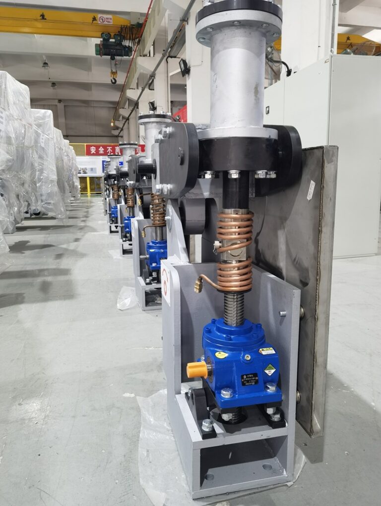
A Screw Jack System for Metal Slitting Machine helps adjust cutter frames, roller positions, machine height, and working gaps in coil processing equipment.
Metal slitting machines cut wide coils into narrower strips. Depending on the production line, they may process carbon steel, stainless steel, aluminum, copper, or other sheet materials.
The actual cutting force comes from the knife shaft and machine frame. However, the adjustment system still plays an important role.
If the cutter frame, roller position, or working gap changes, the machine may produce:
- Uneven strip width
- Larger burrs
- Poor edge quality
- Material deviation
- Faster knife wear
Therefore, stable mechanical adjustment supports the final cutting result.
Why Metal Slitting Machines Need Screw Jacks
A slitting machine often contains heavy cutter frames and roller structures.
Operators may need to adjust them during:
- Knife setup
- Material change
- Thickness change
- Maintenance
- Roller alignment
- Process calibration
Manual adjustment becomes difficult when the structure is large and heavy.
Therefore, engineers may use screw jacks to provide slow and controlled vertical movement.
A screw jack converts rotary motion into linear motion. As a result, the system can adjust the machine structure with better repeatability.
What Does the Gear Reducer Do in a Metal Slitting Machine?
The motor normally runs faster than the adjustment mechanism needs.
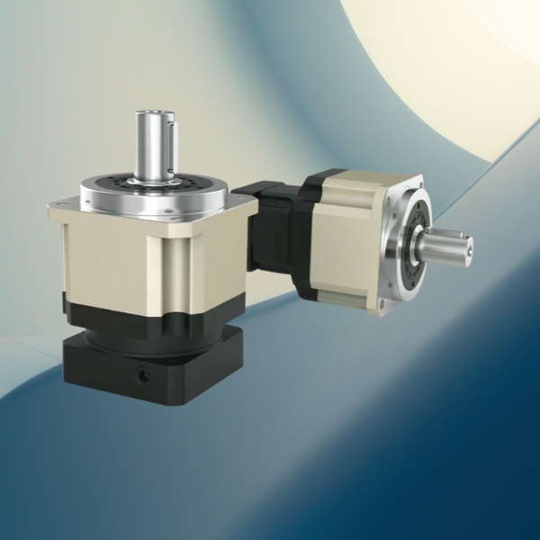
Therefore, the gear reducer reduces speed and increases output torque.
This helps the system achieve:
- Slow adjustment
- Higher torque
- Smooth starting
- Better position control
- Lower mechanical shock
For heavy cutter frames, high speed usually creates more problems than benefits.
A slow adjustment speed gives operators and control systems more time to stop at the correct position.
Common Problem 1: Uneven Cutter Frame Adjustment
Large slitting machines often have adjustment points on both sides.
If one side moves more than the other, the cutter frame may tilt.
This can change:
- Knife overlap
- Knife clearance
- Roller alignment
- Strip path
As a result, the machine may produce poor cutting edges or inconsistent strip width.
Solution: Synchronized Screw Jack Adjustment
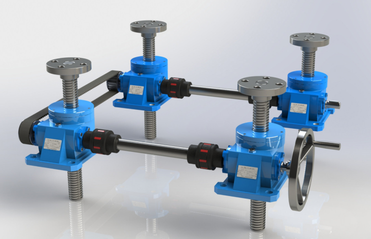
Engineers can connect multiple screw jacks through:
- Shafts
- Couplings
- Gear reducers
- Bevel gearboxes
- Synchronous drives
This design helps both sides move together.
Therefore, the cutter frame remains more level during adjustment.
For more multi-point design logic, see:
How to Size a Multi-Point Screw Jack Lifting System
Common Problem 2: Knife Gap and Overlap Errors
Slitting quality depends strongly on knife setup.
If knife clearance is too large, the strip may develop rough edges and large burrs.
However, if the clearance is too small, knife wear and cutting load may increase.
The same problem applies to knife overlap.
Solution
The adjustment system should provide:
- Stable position control
- Low backlash
- Good guide support
- Repeatable movement
In addition, engineers should separate two functions:
The machine frame carries the cutting force.
The screw jack adjusts the position.
This matters because the screw jack should not automatically carry the full cutting impact.
Common Problem 3: High Starting Torque
A heavy machine structure can create high resistance during startup.
Possible causes include:
- Frame weight
- Guide friction
- Mechanical preload
- Poor alignment
- Lubrication condition
If the motor and reducer have too little torque, the adjustment system may move slowly or vibrate.
Solution
Engineers should check:
- Maximum load
- Starting torque
- Gear ratio
- Motor power
- Service factor
- Transmission efficiency
A suitable reducer helps the screw jack start more smoothly.
In addition, controlled acceleration can reduce shock on the couplings and shafts.
Common Problem 4: Side Load on the Screw Jack
A screw jack mainly works with axial load.
However, a large cutter frame may shift sideways during adjustment if the guide structure lacks stiffness.
This creates side load on the screw.
Over time, side load may cause:
- Screw wear
- Higher friction
- Noise
- Poor positioning
- Shorter service life
Solution
The machine should use a separate guide system.
For example:
- Guide columns
- Linear guides
- Sliding blocks
- Structural guide surfaces
Then the screw jack can focus on lifting, while the guide system handles lateral force.
This design usually improves long-term accuracy.
Common Problem 5: Backlash After Long-Term Operation
Metal slitting equipment often needs repeated adjustment.
After long service, wear may increase backlash in:
- Screw threads
- Gear reducers
- Couplings
- Bearings
- Shaft connections
As a result, the machine may no longer return to the same position.
Solution
Maintenance teams should check backlash regularly.
They should also inspect:
- Screw and nut condition
- Reducer clearance
- Coupling wear
- Bearing play
- Mounting bolts
If the system requires high positioning accuracy, engineers may also use encoders or position sensors.
However, mechanical accuracy should come first.
How Screw Jack Adjustment Affects Slitting Quality
The screw jack does not cut the metal.
Still, it affects several important process conditions.
For example, incorrect frame adjustment may influence:
- Knife height
- Knife gap
- Knife overlap
- Roller pressure
- Strip path
- Machine alignment
Therefore, a poor adjustment system may eventually show up as a cutting-quality problem.
This is why engineers should treat the screw jack system as part of the process-control structure.
How to Select a Screw Jack System for Metal Slitting Machine
A correct Screw Jack System for Metal Slitting Machine selection should start with the real adjustment task.
Load Capacity
Check the actual structure weight.
For multi-point systems, do not simply divide the total load by the number of jacks.
Instead, consider:
- Uneven load
- Center of gravity
- Frame deformation
- Safety factor
Stroke Length
The stroke should match the required adjustment range.
For longer strokes, engineers should also check screw stability and buckling.
Lifting Speed
Slitting equipment usually needs controlled adjustment, not fast lifting.
Therefore, slower speed often gives better positioning.
Duty Cycle
Some machines only adjust during setup.
Others adjust frequently during production.
These two cases require different thermal and lubrication considerations.
Accuracy
Define the required position repeatability before selecting the screw jack and reducer.
Gear Reducer Selection for Slitting Machine Adjustment
The gear reducer should match:
- Motor speed
- Required output speed
- Starting torque
- Screw jack input torque
- Duty cycle
- Installation layout
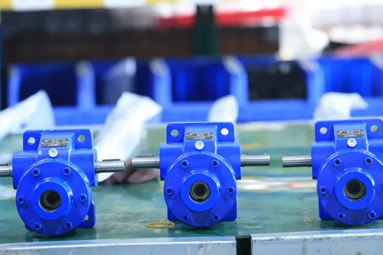
For simple adjustment, a worm gear reducer may provide compact right-angle transmission and a large ratio.
However, for frequent operation or higher efficiency, engineers may consider helical or bevel-helical designs.
The correct choice depends on the application.
Maintenance Problems in Slitting Machine Lifting Systems
Long-term reliability depends on maintenance.
Common issues include:
- Poor lubrication
- Loose bolts
- Worn couplings
- Misalignment
- Gearbox oil leakage
- Screw wear
- Limit switch failure
Maintenance Direction
Regular checks should include:
- Screw lubrication
- Gearbox temperature
- Oil condition
- Coupling alignment
- Bolt tightness
- Abnormal noise
- Travel limit function
For gearbox leakage and lubrication problems, see:
Gearbox Oil Leakage: Causes, Prevention and Fast Repair Methods
Safety in Metal Slitting Machines
Metal slitting equipment contains:
- Sharp rotary knives
- Nip points
- Moving rollers
- Rotating shafts
- Heavy moving structures
Therefore, safety design matters.
Engineers should consider:
- Emergency stops
- Mechanical guards
- Interlocked covers
- Upper and lower travel limits
- Overload protection
- Lockout procedures
- Safe maintenance access
For general machine risk assessment, refer to:
ISO 12100 Safety of Machinery
OSHA also provides guidance on guarding dangerous machine parts and rotating equipment:
OSHA Machine Guarding
Why Mechanical Alignment Matters More Than Simply Adding Motor Power
When a slitting machine becomes difficult to adjust, the first idea is often to use a larger motor.
However, more motor power does not fix:
- Poor guide alignment
- Uneven loading
- Excessive backlash
- Bent frames
- Worn screw threads
Therefore, engineers should check the complete mechanical structure first.
A properly aligned system usually needs less torque and lasts longer.
Related Metal Processing Applications
The same screw jack and gearbox logic applies to:
- Cut-to-length lines
- Coil processing equipment
- Steel strip lines
- Aluminum slitting machines
- Roll forming machines
- Leveling machines
- Recoiling equipment
- Heavy roller adjustment systems
Related internal reading:
Screw Jack Selection Guide
Multi-Point Screw Jack Lifting System
Gearbox Oil Leakage Guide
NUODUN Products
Conclusion
A Screw Jack System for Metal Slitting Machine does not perform the cutting itself.
Instead, it helps keep the cutter frame, roller position, and working gap stable and repeatable.
The main engineering challenges include:
- Uneven adjustment
- High starting torque
- Side load
- Backlash
- Long-term wear
- Position accuracy
Therefore, engineers should treat the motor, gear reducer, screw jack, guides, and machine frame as one complete system.
Good slitting quality depends on sharp knives.
But it also depends on keeping those knives in the right position every time.