whatsapp:+86 13622680352



Worm Gear Reducer for Roller Coating Machine
A Worm Gear Reducer for Roller Coating Machine helps control roller speed, increase output torque, and maintain stable material feeding during PU and other industrial coating processes.
Roller coating equipment often uses several rollers for feeding, coating, pressing, spreading, and transferring material. However, these rollers do not always run at exactly the same speed.
Instead, each roller may need a different speed according to its process function.
Therefore, many roller coating machines use separate motor and gearbox units for different roller groups. This design gives engineers more control over roller speed, torque, and process adjustment.
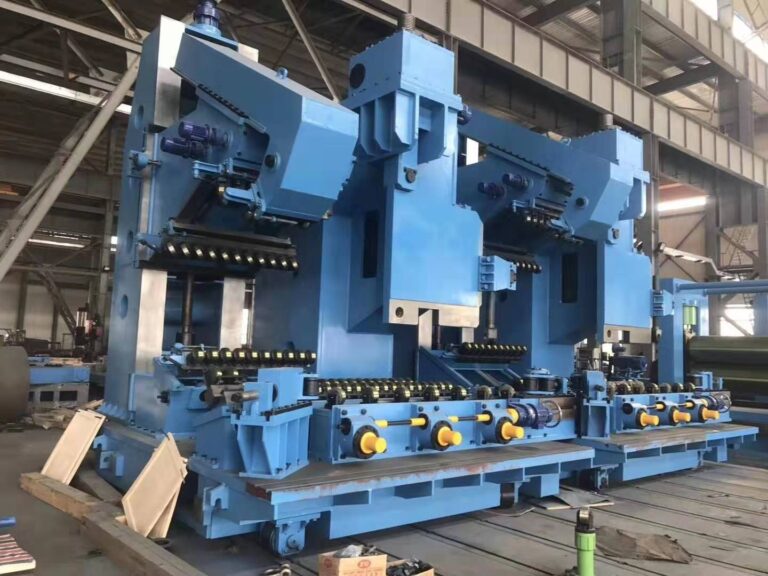
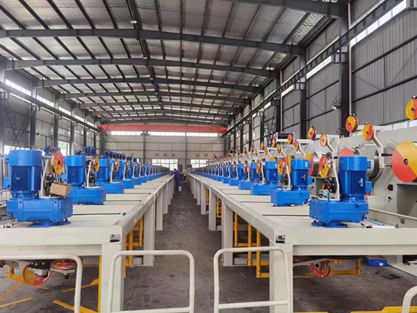
In the equipment shown here, multiple motor and worm gear reducer units create a compact multi-roller drive system.
Why Does a Roller Coating Machine Need Gear Reducers?
An electric motor usually runs much faster than the coating roller requires.
Therefore, the gearbox reduces motor speed while increasing output torque.
This helps the machine achieve:
- Stable low-speed roller rotation
- Higher output torque
- Smooth acceleration
- Better material feeding
- Easier individual roller adjustment
- More stable coating conditions
For coating equipment, this matters because roller movement directly affects the contact between the coating material, roller, and workpiece.
If roller speed changes unexpectedly, coating quality may also change.
How Roller Speed Affects PU Coating Quality
Roller coating depends on controlled contact.
For example, coating thickness may change according to:
- Roller speed
- Speed difference between rollers
- Roller pressure
- Coating viscosity
- Roller gap
- Material feeding speed
Therefore, transmission stability becomes part of process control.
If the roller runs too fast, coating transfer may become unstable.
However, if the roller runs too slowly, the machine may apply too much material or reduce production speed.
As a result, engineers need both mechanical reduction and motor speed control to maintain the correct operating range.
Why Use Independent Gear Motors for Multiple Rollers?
One noticeable feature of this roller coating machine is the use of several independent motor and gearbox units.
This arrangement offers an important advantage: each roller can use its own drive setting.
Different rollers may perform different jobs.
For example:
- Feeding roller
- Metering roller
- Coating roller
- Pressing roller
- Transfer roller
Therefore, one common speed does not always suit the entire machine.
With independent gear motors, engineers can adjust the speed of each roller according to the coating process.
This helps improve:
- Coating thickness control
- Material transfer
- Roller pressure stability
- Process flexibility
- Product consistency
Why Worm Gear Reducers Fit Roller Coating Equipment
A worm gear reducer offers several practical advantages in this application.
Compact Right-Angle Drive
Roller coating machines often install several motors close together.
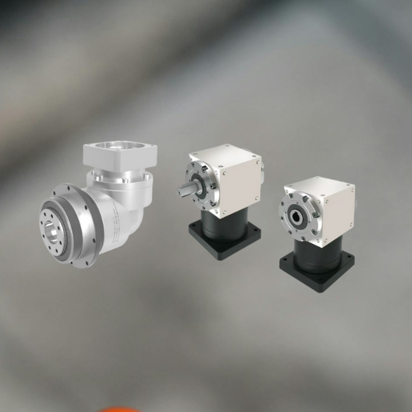
A worm reducer changes the transmission direction by 90 degrees. Therefore, engineers can place the motor beside the roller instead of extending the complete drive system outward.
This saves machine space.
Large Reduction Ratio
Coating rollers usually need lower speed than standard electric motors.
A worm gearbox can provide a relatively large reduction ratio in a compact housing.
Therefore, it works well for slow roller movement.
Smooth Motion
Worm gear transmission provides smooth rotary movement.
For coating machines, smoother transmission helps reduce sudden speed changes and unnecessary vibration.
Practical Cost
A helical or servo gearbox may provide higher efficiency or precision. However, many roller coating applications do not need the highest possible transmission efficiency.
If the torque, speed, duty cycle, and temperature remain within the gearbox limits, a worm gear reducer often provides a practical balance between:
- Cost
- Size
- Performance
- Maintenance
- Installation flexibility
Good engineering does not require the most expensive gearbox. It requires the gearbox that fits the process.
Common Problem 1: Uneven Coating Thickness
Uneven coating thickness is one of the most important quality problems in roller coating.
Possible causes include:
- Unstable roller speed
- Incorrect speed ratio between rollers
- Roller gap error
- Uneven pressure
- Coating viscosity changes
- Roller surface wear
Solution
Engineers should first separate mechanical problems from process problems.
For the drive system, they should check:
- Motor speed
- Gear ratio
- Reducer backlash
- Roller shaft condition
- Coupling alignment
- Bearing condition
In addition, variable-frequency control can help adjust individual roller speeds when the process needs different operating conditions.
Stable transmission cannot solve every coating problem, but it creates the mechanical foundation for repeatable coating quality.
Common Problem 2: Roller Slipping Under Load
As material thickness, coating resistance, or roller pressure changes, the drive system may need more torque.
If the gearbox does not provide enough torque, roller speed may fall.
This can cause:
- Material slipping
- Unstable feeding
- Coating marks
- Thickness variation
- Motor overload
Solution
Engineers should calculate gearbox torque according to the maximum working condition rather than the normal average load.
Important inputs include:
- Roller diameter
- Roller width
- Roller pressure
- Line speed
- Material resistance
- Starting torque
- Gear ratio
- Motor power
In addition, engineers should keep a suitable service factor for startup and short-term load changes.
Common Problem 3: Different Roller Speeds Cause Process Instability
A roller coating machine may intentionally run different rollers at different speeds.
However, uncontrolled speed differences can create problems.
For example, excessive speed difference may increase shear, coating transfer variation, or material tension.
Solution
Engineers should define the required speed relationship between each roller before selecting the gearbox ratio.
Then, they can use motor frequency control for fine adjustment.
A practical control concept is:
Gear ratio provides the basic mechanical speed range, while the motor controller provides process adjustment.
This approach avoids asking the variable-frequency drive to compensate for a badly selected gearbox.
Common Problem 4: Worm Gear Reducer Overheating
Worm gear reducers use sliding contact between the worm and worm wheel.
Therefore, they generally produce more heat than high-efficiency helical gear reducers.
This becomes important when the roller coating machine runs continuously.
Possible overheating causes include:
- Excessive load
- Too high input speed
- Wrong gearbox size
- Poor lubrication
- Low lubricant level
- Limited ventilation
- Excessive duty cycle
Solution
Engineers should check thermal capacity during gearbox selection.
They should also monitor:
- Housing temperature
- Lubricant condition
- Oil leakage
- Bearing noise
- Motor current
For related maintenance information, see Gearbox Oil Leakage: Causes, Prevention and Fast Repair Methods.
If continuous operation creates too much heat, engineers may need a larger gearbox or a more efficient helical or hypoid transmission.
Worm Gear Reducer vs Helical Gear Reducer for Coating Machines
A worm reducer is not automatically the best solution for every roller.
Therefore, engineers should compare the actual duty.
Worm Gear Reducer
It works well when the machine needs:
- Compact right-angle transmission
- Large reduction ratio
- Moderate speed
- Moderate duty cycle
- Simple installation
Helical Gear Reducer
It may offer advantages when the machine needs:
- Higher efficiency
- Long continuous operation
- Higher power
- Lower operating temperature
- Higher mechanical efficiency
Therefore, a coating machine may even use different gearbox types for different mechanisms.
The main roller drive may benefit from a high-efficiency gearbox, while adjustment or auxiliary rollers may work well with worm reducers.
How to Select a Gear Reducer for Roller Coating Machine
Engineers should collect the real process data before selecting a gearbox.
Roller Speed
First, confirm the required roller rpm.
Then, select a reduction ratio that keeps the motor inside a practical speed range.
Output Torque
Calculate the torque required under maximum roller resistance.
Do not use only the normal running load.
Duty Cycle
Confirm whether the roller runs:
- Occasionally
- Several hours per shift
- Continuously
Continuous-duty applications require more attention to gearbox temperature.
Roller Diameter and Width
Larger and wider rollers usually increase inertia and torque requirements.
Installation Space
Multi-roller machines often have very limited drive space.
Therefore, gearbox dimensions and motor orientation matter.
Environmental Conditions
Coating equipment may operate around:
- PU materials
- Adhesives
- Dust
- Cleaning agents
- Oil mist
Therefore, engineers should consider seals, surface protection, and maintenance access.
More gearbox and gear motor configurations are available through NUODUN transmission products.
Maintenance of Roller Coating Gearbox Systems
Regular maintenance helps keep roller speed stable.
Maintenance teams should check:
- Gearbox lubrication
- Oil seals
- Roller bearings
- Motor current
- Gearbox temperature
- Mounting bolts
- Shaft alignment
- Abnormal noise
In addition, operators should record changes in coating quality.
Sometimes a coating defect appears before a gearbox develops obvious noise or failure.
For example, gradual backlash or bearing wear may first appear as small roller-speed or pressure changes.
Therefore, coating quality data can also provide an early sign of mechanical problems.
Safety Around Roller Coating Machines
Roller coating machines contain rotating rollers, nip points, shafts, couplings, and motor-driven transmission parts.
Therefore, guarding deserves special attention.
OSHA notes that moving machine parts can cause serious injuries and that machine functions or processes capable of causing injury require suitable safeguards.
Engineers should consider:
- Roller nip-point guards
- Gearbox and coupling guards
- Emergency stops
- Interlocked access covers
- Safe cleaning procedures
- Lockout procedures during maintenance
For broader machine design and risk-reduction principles, ISO 12100 provides a methodology for identifying hazards and reducing machinery risks.
External references: ISO 12100 — Safety of Machinery and OSHA Machine Guarding.
Related Roller and Gearbox Applications
The same transmission principles apply to:
- PU coating machines
- Adhesive coating equipment
- Laminating machines
- Film coating lines
- Wood panel coating machines
- Textile coating equipment
- Printing rollers
- Feeding and pressing machines
For another continuous-production gearbox application, see Gear Motor & Gearbox in Chemical Powder Processing Systems.
Conclusion
A Worm Gear Reducer for Roller Coating Machine does more than reduce motor speed.
It helps control roller torque, feeding stability, coating transfer, and machine layout.
However, reliable coating performance depends on the complete system.
Engineers should consider roller speed, torque, gear ratio, duty cycle, temperature, motor control, roller pressure, and maintenance conditions together.
For multi-roller PU coating equipment, independent motor and gearbox drives provide a practical way to control different roller functions.
The key is not simply making every roller rotate.
The goal is to make every roller rotate at the right speed, with the right torque, for the right coating process.