whatsapp:+86 13622680352



Gear Reducer for Welding Positioner
A Gear Reducer for Welding Positioner helps robotic welding systems rotate, tilt, or turn heavy workpieces into the correct welding position.
In an automated welding cell, the robot controls the welding torch. However, the positioner controls the workpiece.
This matters because many welds become easier and more consistent when the system places the joint in an ideal welding position.
A typical welding positioner may include:
- Motor
- Gear reducer
- Rotary table
- Bearings
- Fixture
- Encoder
- Brake
- Robot control system
The motor provides motion, while the gearbox reduces speed and increases torque. As a result, the positioner can rotate a heavy fixture slowly and stop it at a controlled angle.
Why a Welding Positioner Needs a Gear Reducer
A welding fixture may carry a large steel structure, frame, tank, bracket, or fabricated part.
Therefore, direct motor drive is often unsuitable.
The positioner usually needs:
- Low rotational speed
- High output torque
- Smooth acceleration
- Stable stopping
- Accurate angular position
- Reliable load holding
A gear reducer helps match the high-speed motor with the low-speed rotary table.
In addition, the reducer increases available torque, which becomes especially important when the workpiece has high inertia or an off-center center of gravity.
Problem 1: High Starting Torque and Workpiece Inertia
One of the biggest challenges in a welding positioner is inertia.
A heavy fixture may not require extremely high torque after it reaches a constant speed. However, starting and stopping the fixture can require much more torque.
The problem becomes more serious when:
- The workpiece is large
- The fixture is heavy
- The load sits far from the rotation center
- Acceleration is too fast
- The positioner rotates frequently
Solution
Engineers should calculate the drive based on the complete rotating mass, not only the workpiece weight.
They should consider:
- Workpiece weight
- Fixture weight
- Center of gravity
- Rotation radius
- Acceleration time
- Required speed
- Starting torque
- Gear ratio
A suitable gear reducer provides enough torque reserve while allowing smoother acceleration.
Therefore, the motor and gearbox should work as one system rather than two separately selected parts.
Problem 2: Eccentric Load on the Welding Positioner
Real welding fixtures rarely have perfectly balanced loads.
For example, a large fabricated frame may place most of its mass on one side of the rotary axis.
This creates an eccentric load.
As a result, the drive system may experience:
- Higher peak torque
- Uneven bearing load
- More vibration
- Increased gearbox stress
- Poor stopping stability
Solution
Engineers should check the center of gravity before selecting the gearbox.
If possible, the fixture design should bring the workpiece center of gravity closer to the rotation axis.
This can reduce:
- Required motor torque
- Gearbox load
- Bearing stress
- Energy consumption
- Mechanical vibration
Sometimes improving fixture balance provides more value than simply selecting a larger gearbox.
Gear Reducer Backlash and Welding Position Accuracy
Robotic welding often requires the positioner to rotate to a fixed angle and stop repeatedly.
For example:
- 0°
- 45°
- 90°
- 180°
If the gearbox has excessive backlash, the final table position may change slightly after each movement.
That can affect:
- Weld path alignment
- Torch position
- Robot calibration
- Repeatability
- Weld consistency
Solution
Engineers should define the required positioning accuracy before choosing the reducer.
They should evaluate:
- Gearbox backlash
- Rotary bearing clearance
- Coupling stiffness
- Fixture stiffness
- Encoder resolution
- Servo control accuracy
For higher-precision robotic welding, a servo motor with encoder feedback can improve positioning.
However, mechanical backlash still matters.
A control system cannot completely compensate for a loose mechanical transmission chain.
Problem 3: Shock During Start and Stop
A welding positioner often performs repeated indexing movements.
If the system starts or stops too quickly, inertia creates mechanical shock.
Over time, this shock may affect:
- Gear teeth
- Bearings
- Couplings
- Mounting bolts
- Fixture structure
- Rotary table
Solution
A suitable reduction ratio combined with controlled acceleration and deceleration helps reduce impact.
Engineers should avoid treating the positioner like a simple ON/OFF motor application.
Instead, smooth acceleration allows the system to build torque gradually.
Likewise, smooth deceleration helps the fixture stop without excessive vibration.
This becomes especially important for large welding structures.
Position Holding and Safety in Welding Turnover Tables
After the welding positioner reaches the required angle, it must remain stable while the robot performs welding.
Unwanted movement may affect both welding quality and safety.
Therefore, engineers should consider:
- Motor brake
- Mechanical brake
- Gearbox holding characteristics
- Position lock
- Emergency stop
- Power-loss behavior
Some worm gear systems can provide good resistance to reverse motion under certain operating conditions.
However, designers should not automatically treat worm gearing as a certified safety brake.
If falling or uncontrolled rotation could create a hazard, the machine should use a proper braking or mechanical holding solution.
Gear Reducer Types for Welding Positioners
Different positioners may use different gearbox designs.
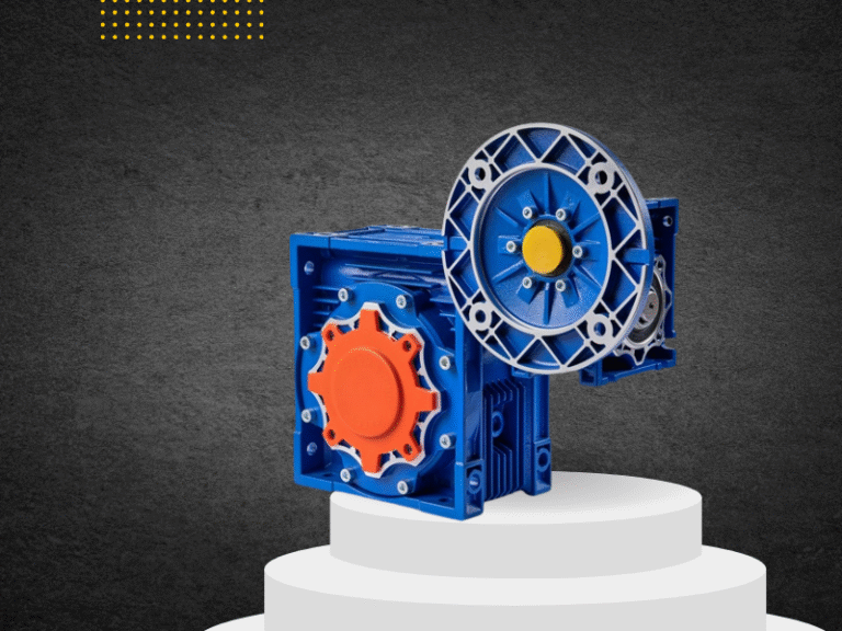
Worm Gear Reducer
A worm gearbox offers:
- Compact right-angle transmission
- Large reduction ratio
- Smooth low-speed operation
- Simple structure
Therefore, it can work well for moderate-load welding tables and auxiliary positioning mechanisms.
Helical or Bevel Helical Gearbox
A helical gearbox provides:
- Higher efficiency
- Lower heat generation
- Good continuous-duty performance
- High torque capability
Therefore, it may suit larger positioners that rotate frequently.
Planetary Gearbox
A planetary gearbox provides:
- High torque density
- Compact size
- Low backlash options
- Good positioning performance
As a result, it works well in higher-precision servo positioning systems.
The correct gearbox depends on torque, speed, accuracy, duty cycle, cost, and machine layout.
Continuous Operation and Gearbox Temperature
Automated welding lines may perform hundreds or thousands of positioning cycles.
Therefore, gearbox thermal performance matters.
Common causes of excessive temperature include:
- Overload
- Incorrect gearbox size
- High input speed
- Poor lubrication
- Frequent acceleration
- Poor ventilation
- Bearing problems
Solution
Maintenance teams should monitor:
- Gearbox housing temperature
- Lubricant condition
- Bearing noise
- Oil leakage
- Motor current
- Abnormal vibration
For related maintenance information, see the Gearbox Oil Leakage Guide.
A gearbox that repeatedly overheats may require a larger size, lower input speed, better lubrication, or a more efficient transmission design.
How to Select a Gear Reducer for Welding Positioner
A correct Gear Reducer for Welding Positioner selection starts with the real load.
Workpiece and Fixture Weight
Include both the part and the fixture.
Center of Gravity
A load far from the rotation axis increases required torque.
Rotation Speed
Welding positioners usually need controlled low-speed movement rather than high speed.
Acceleration Time
Fast acceleration increases peak torque.
Therefore, slower controlled acceleration can reduce gearbox size and mechanical shock.
Gear Ratio
The gear ratio should provide the required table speed while keeping the motor in a suitable operating range.
Backlash
Higher positioning accuracy usually requires lower gearbox backlash.
Duty Cycle
Frequent indexing or continuous rotation requires stronger thermal performance.
Service Factor
Welding equipment may experience repeated starts, eccentric load, vibration, and long working cycles.
Therefore, the gearbox should have suitable load margin.
More transmission configurations can be found in NUODUN transmission products.
Why the Rotary Table Bearing Also Matters
The gearbox should not carry every structural load by itself.
The rotary table and bearing system should support:
- Workpiece weight
- Radial load
- Axial load
- Overturning moment
The gearbox mainly provides drive torque.
If the gearbox output shaft must also carry large bending or overturning loads, bearing life and transmission accuracy may decrease.
Therefore, a good positioner separates two functions:
Bearings support the load.
The gearbox provides the motion.
This design usually improves reliability.
Robot and Positioner Synchronization
In advanced welding cells, the robot and positioner may move at the same time.
This allows the system to maintain an ideal welding angle while following complex seams.
However, coordinated motion requires:
- Accurate encoder feedback
- Stable gearbox transmission
- Low backlash
- Correct calibration
- Reliable communication between controllers
Therefore, the positioner becomes an additional robot axis rather than a simple rotating table.
In these applications, mechanical transmission accuracy directly affects robotic welding accuracy.
Safety Considerations for Robotic Welding Positioners
A welding positioner combines rotating heavy loads with robotic motion.
Therefore, the machine must control hazards around:
- Rotating fixtures
- Pinch points
- Robot operating zones
- Cables
- Welding arcs
- Unexpected startup
For general machine risk assessment and risk reduction, engineers can refer to ISO 12100 Safety of Machinery.
OSHA also provides guidance on Machine Guarding, including protection from rotating parts and other mechanical hazards.
Depending on the complete robotic cell, designers should also follow the applicable robot safety requirements and local regulations.
Common Welding Positioner Maintenance Checks
Regular maintenance helps maintain positioning accuracy.
Maintenance teams should inspect:
- Gearbox lubrication
- Rotary bearings
- Fixture bolts
- Couplings
- Motor brake
- Encoder
- Gearbox backlash
- Cable routing
- Abnormal noise
- Table vibration
In addition, engineers should monitor changes in welding accuracy.
If a robot program has not changed but weld position begins to drift, mechanical backlash or fixture movement may be part of the cause.
Related Applications
The same transmission principles also apply to:
- Welding turnover tables
- Tank welding positioners
- Robotic welding cells
- Pipe welding positioners
- Headstock and tailstock positioners
- Rotary assembly fixtures
- Heavy fabrication positioners
- Automated handling systems
Conclusion
A Gear Reducer for Welding Positioner does much more than slow down a motor.
It helps the positioner control heavy loads, overcome inertia, reduce mechanical shock, maintain angular position, and support robotic welding repeatability.
The main engineering challenges include:
- High starting torque
- Eccentric load
- Backlash
- Position holding
- Frequent start-stop cycles
- Heat generation
- Long-term accuracy
Therefore, engineers should evaluate the complete drive chain:
Motor → Gear Reducer → Rotary Table → Bearing → Fixture → Workpiece
The best welding positioner does not simply rotate a workpiece.
It places the weld in the right position — smoothly, accurately, and repeatedly.