whatsapp:+86 13622680352

Daily Operating Fault Diagnosis Methods for Gear Reducers
Introduction: Why Daily Fault Diagnosis Matters for Gear Reducers
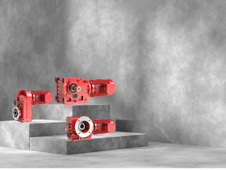
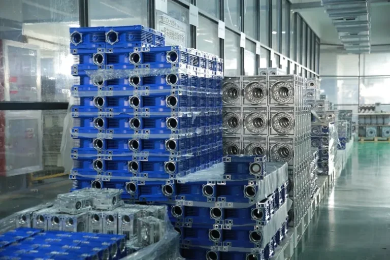
Gear reducers (gearboxes) are core components in industrial transmission systems, widely used in manufacturing lines, conveyors, robotics, energy systems, and heavy machinery. Their operating condition directly affects system efficiency, uptime, and safety.
However, gear reducers often operate under continuous load, variable speed, high torque, and harsh environments, making them vulnerable to wear, lubrication failure, and alignment issues. Without effective daily fault diagnosis, minor abnormalities can escalate into catastrophic failures, leading to unplanned downtime and costly repairs.
Effective fault diagnosis is therefore a cornerstone of preventive maintenance, and the most reliable approach combines:
- Instrument-based quantitative detection, and
- Experience-driven qualitative inspection
This article provides a structured, field-proven methodology for daily gear reducer fault diagnosis, suitable for maintenance engineers, equipment managers, and OEM users.

1. Core Principles of Gear Reducer Fault Diagnosis
Before discussing specific methods, it is essential to understand the fundamental objectives of fault diagnosis:
- Detect abnormalities early
- Identify root causes, not just symptoms
- Track trend changes over time
- Prevent secondary damage to gears, bearings, and shafts
An effective diagnosis system focuses on key operating parameters—temperature, vibration, lubrication condition, and noise characteristics—while maintaining standardized inspection records.
2. Instrument-Based Precision Detection
2.1 Temperature Monitoring of Bearings and Gearbox Housing
Bearing temperature is one of the most direct indicators of gearbox health.
Normal Temperature Range
- Typical bearing operating temperature: 40–80°C
- Warning threshold: Above 85°C
- Critical condition: Rapid temperature rise or abnormal fluctuations
Best Practices for Temperature Measurement
- Measure under different operating conditions (no-load, rated load, peak load)
- Record temperature trends, not just single values
- Use infrared thermometers, thermal cameras, or built-in sensors where available
A sudden temperature increase may indicate:
- Insufficient lubrication
- Bearing wear or seizure
- Excessive preload
- Misalignment or overloading
Any reading exceeding the safe threshold should trigger immediate shutdown and inspection.
2.2 Vibration Monitoring and Analysis
Vibration analysis provides early warning of mechanical issues long before visible damage occurs.
Key Monitoring Indicators
- Overall vibration amplitude
- Frequency spectrum changes
- Irregular or impulsive vibration patterns
Reference Standards
- Compare readings with factory baseline values
- A vibration deviation exceeding ±0.1 mm or showing unstable oscillation is considered abnormal
Common Fault Indicators
- Abnormal vibration + noise → gear meshing problems
- High-frequency vibration → bearing defects
- Periodic vibration → shaft misalignment or eccentricity
Regular vibration measurement using portable inspection instruments significantly improves fault prediction accuracy.
2.3 Inspection Record Standardization
To enable trend analysis and traceability, inspections must be documented systematically.
Recommended record structure:
- Equipment ID
- Inspection date and time
- Operating conditions
- Measured values
- Inspector name
- Observed abnormalities
This data-driven approach supports predictive maintenance and long-term reliability optimization.
3. Experience-Based Manual Diagnosis Methods
When professional instruments are unavailable—or as a complementary measure—manual inspection remains highly effective. A structured “Observe – Touch – Listen” method is widely used in the field.
3.1 Visual Inspection (Observation Method)
Visual checks focus on lubrication, sealing, and external integrity.
Key Inspection Points
- Oil leakage: Check seals, oil plugs, and joint surfaces
- Vent plug condition: Ensure breathing holes are not blocked by dust or oil sludge
- Oil level: Verify oil is within the min–max range on the sight glass
- Oil quality:
- Darkened oil → oxidation or overheating
- Milky oil → moisture contamination
- Sediment → internal wear debris
Internal Inspection (During Scheduled Shutdown)
- Gear tooth surfaces: pitting, scuffing, wear, broken teeth
- Bearings: cracks on inner/outer races, discoloration
- Housing interior: abnormal debris accumulation
Visual inspection provides direct evidence of mechanical degradation and should never be overlooked.
3.2 Temperature Assessment by Touch
A simple yet effective qualitative method is checking temperature by hand.
Proper Technique
- Use the back of the hand
- Lightly touch the bearing end cover
- Avoid contact with rotating parts
Judgment Criteria
- Can touch for more than 3 seconds without discomfort → normal
- Strong burning sensation or inability to touch → abnormal
Excessive surface temperature often indicates lubrication failure or internal friction and requires immediate investigation.
3.3 Acoustic Diagnosis (Listening Method)
Sound characteristics provide valuable clues about internal conditions.
Normal Operating Sound
- Smooth, continuous “humming” noise
- No sharp, intermittent, or metallic sounds
Abnormal Noise Indicators
- Squeaking or rubbing → insufficient lubrication, seal interference
- Knocking or clicking → excessive gear backlash, chipped teeth
- Grinding or sand-like noise → foreign particles or bearing race wear
For better accuracy, technicians often use a screwdriver or metal rod as a sound conductor, placing one end against the gearbox housing and the other near the ear.
4. Common Gear Reducer Faults and Likely Causes
| Symptom | Possible Cause |
|---|---|
| High temperature | Poor lubrication, overload, bearing failure |
| Excessive vibration | Gear wear, misalignment, loose mounting |
| Abnormal noise | Gear damage, bearing wear, contamination |
| Oil leakage | Seal aging, blocked breather, overfilled oil |
| Rapid oil deterioration | Overheating, moisture ingress |
Early diagnosis allows corrective action before irreversible damage occurs.
5. Preventive Maintenance Recommendations
- Implement daily, weekly, and monthly inspection schedules
- Replace lubricants according to operating conditions
- Use condition-based maintenance instead of reactive repair
- Train operators to recognize early warning signs
- Maintain historical data for trend comparison
A well-maintained gear reducer can achieve significantly longer service life and higher transmission efficiency.
6. Frequently Asked Questions (FAQ)
Q1: How often should a gear reducer be inspected?
Daily visual and sound checks are recommended, with detailed instrument inspections conducted weekly or monthly depending on operating severity.
Q2: What is the most common cause of gear reducer failure?
Lubrication issues remain the leading cause, followed by overloading and misalignment.
Q3: Can manual inspection replace vibration analysis?
No. Manual inspection is valuable but should complement—not replace—instrument-based diagnostics for accurate fault prediction.
Q4: When should a gear reducer be shut down immediately?
Immediate shutdown is required if bearing temperature exceeds 85°C, vibration increases sharply, or abnormal impact noises occur.
Q5: Are OEM gear reducers more difficult to maintain?
Not necessarily. OEM gear reducers designed by experienced manufacturers often offer better compatibility, documentation, and service support.
Conclusion: Reliable Diagnosis Ensures Long-Term Performance
Daily fault diagnosis is not a one-time task but a continuous process that safeguards operational stability. By integrating instrument-based monitoring with experienced field judgment, maintenance teams can detect problems early, reduce downtime, and extend equipment lifespan.
A structured diagnostic strategy is essential for modern industrial transmission systems.
NUODUN is a professional power transmission equipment manufacturer, specializing in high-performance gear reducers and customized drive solutions.