whatsapp:+86 13622680352

Why Gearbox Shaft Breakage Happens: Causes, Engineering Solutions
Shaft breakage is one of the most frequent and costly mechanical failures in industrial automation. Many users experience a similar scenario: a system runs normally for several weeks or months, and then suddenly the motor shaft or gearbox output shaft snaps. The damage looks severe, but in most cases the underlying cause is not material quality—it is stress, misalignment, or improper application.
Gearbox and motor shafts rarely fail without warning. Instead, they slowly accumulate microscopic fatigue damage until the final fracture occurs. Understanding these mechanisms is essential for maintaining reliable mechanical systems and preventing expensive downtime.
This article explains why shafts break, how to correctly diagnose the failure mode, and what engineering practices can eliminate these issues. The content is based on actual industrial experience and the long-term gearbox development expertise of NUODUN, a transmission-equipment manufacturer supporting OEM/ODM customization.
1. Misalignment: The Most Common Cause of Shaft Breakage
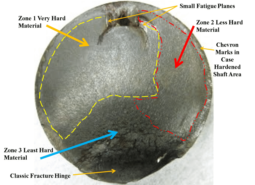
In most cases, broken shafts display a very recognizable fracture pattern:
- The outer ring of the fracture surface is bright and smooth
- The inner region becomes dark and rough
- The center contains granular “final rupture” marks
This pattern is classic bending fatigue, caused by misalignment between the motor shaft and the gearbox input bore.
How Misalignment Creates Bending Fatigue
When the shaft is perfectly aligned:
- It only transmits torque
- Rotation is smooth
- No bending force is applied
But when misalignment exists—even just 0.1–0.3 mm:
- The shaft experiences a strong radial force
- This force bends the shaft once every revolution
- The bending direction continuously changes
- Heat and micro-fractures form at the shaft surface
- Metal structure weakens until the shaft breaks
The worse the misalignment, the faster the shaft fails.
Misalignment not only stresses the motor shaft—it also loads the gearbox input shaft and bearings. If radial force exceeds design limits, the gearbox may deform or break as well.
Why Misalignment Appears During Installation
From an assembly standpoint:
- When aligned, the motor shaft and gearbox bore fit smoothly with full surface contact
- When misaligned, surfaces touch unevenly, leaving gaps
- These gaps allow movement, producing radial force and early fatigue
This is why precision alignment tools—dial indicators, laser alignment, and proper coupling selection—are recommended for professional installations.
2. Why Gearbox Output Shafts Are Even More Vulnerable
Motor shafts transmit relatively small torque.
However, the gearbox output shaft transmits: Toutput=Tmotor×reduction ratioT_{\text{output}} = T_{\text{motor}} \times \text{reduction ratio}Toutput=Tmotor×reduction ratio
This means:
- Higher torque
- Higher stress
- Higher likelihood of breakage
Any small misalignment, poor mounting, unbalanced coupling, or improper belt tension can dramatically shorten the output shaft’s life.
In real applications, users often observe gearbox output shafts breaking first—especially in systems with belts, pulleys, or offset loads.
3. Shaft Breakage Due to Incorrect Gearbox Selection
Even if alignment is perfect, the gearbox itself may be undersized. Many users mistakenly believe:
“As long as the rated output torque meets the requirement, the gearbox will work.”
This is a dangerous misconception.
Correct Engineering Selection Principles
① Motor rated torque × reduction ratio must be LESS than gearbox rated torque
If the motor’s overload capability is strong, it may continue increasing torque during a jam, eventually twisting the shaft apart.
② Maximum working torque must be LESS than 2× the gearbox rated torque
This rule protects:
- Gear teeth
- Bearings
- The output shaft
- The entire powertrain
In duty cycles with frequent acceleration, reversing, or heavy-inertia loads, this rule is critical.
What Happens When Gearbox Torque Capacity Is Too Low
If the load becomes stuck or increases suddenly:
- The motor enters overload mode
- Torque rapidly rises
- The gearbox output shaft exceeds its yield limit
- The shaft twists or snaps
A properly sized gearbox with sufficient torque margin avoids catastrophic failure.
4. Shock Loads and Dynamic Torque: Hidden Causes of Instant Breakage
Dynamic loads during:
- Acceleration
- Deceleration
- Emergency stops
- Reverse motion
- Heavy-inertia starting
…can easily exceed 2× or even 3× rated torque.
This instantaneous torque spike creates:
- Shear stress at the keyway
- Bending at the shaft fillet
- Stress concentration at coupling connections
If the shaft has already accumulated fatigue damage, even a single shock event can finish it off.
Systems with variable-speed drives, robotics, conveyors, or presses are especially prone to these conditions.
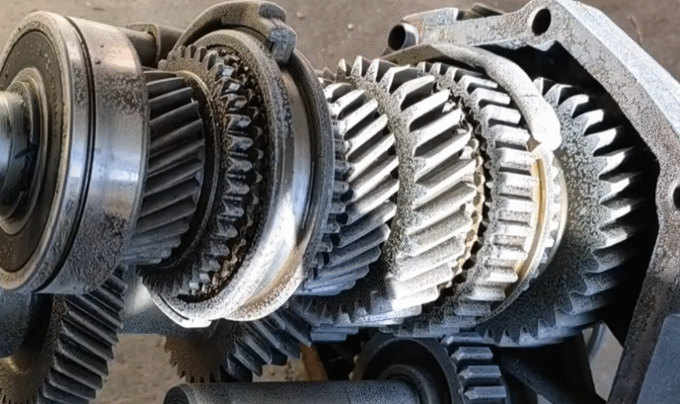
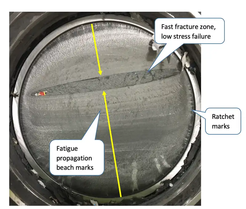
5. Case Study: How Fatigue Crack Transforms Into Complete Shaft Failure
Observed fracture pattern:
- Left side: smooth fatigue “beach marks”
- Right side: rough surface from sudden torsional overload
- Crack always begins at the outer diameter and grows inward
This indicates the shaft reached a point where:
- A progressively growing fatigue crack weakened the structure
- A final overload caused complete rupture
Root cause: Excessive bending + micro-movement at the keyway
Bending stress causes the key and keyway to rub against each other.
This friction leads to:
- Heat
- Wear
- Micro-cracking
- Surface crack initiation
Typical sources of such conditions:
- Poor alignment
- Excessive vibration
- Unbalanced coupling
- Overloading
- Incorrect gearbox selection
Recommended corrective actions:
- Verify actual load torque and working cycle
- Re-check motor–gearbox alignment
- Ensure the coupling is dynamically balanced
- Increase gearbox torque margin for demanding conditions
6. Engineering Measures to Prevent Shaft Breakage
① Guarantee perfect alignment
Use:
- Laser alignment tools
- Dial indicators
- Proper mounting surfaces
- Flexible couplings within allowable offset limits
② Increase torque margin
A practical rule: Tmax load≤0.5×Tgearbox ratedT_{\text{max load}} \leq 0.5 \times T_{\text{gearbox rated}}Tmax load≤0.5×Tgearbox rated
③ Avoid excessive radial and axial loads
Unsupported pulleys or over-tensioned belts cause early shaft failure.
④ Use soft-start and controlled acceleration
Reduces impact torque and extends gearbox life.
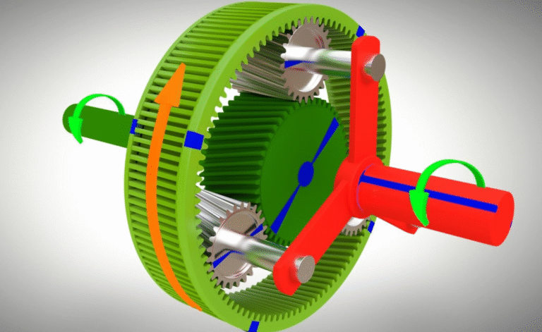
⑤ Choose the correct reducer type
Planetary reducers offer higher rigidity and torque density.
⑥ Ensure proper lubrication and maintenance
Although many precision reducers are maintenance-free, mounting environment still matters.
FAQs: Common Questions About Shaft Breakage
1. Why does a motor shaft break even when torque is low?
Because misalignment introduces bending stress, leading to fatigue failure over time.
2. Can a gearbox shaft break without exceeding rated torque?
Yes. Fatigue, shock loads, and poor alignment can break a shaft long before torque limits are reached.
3. Does a flexible coupling fix misalignment?
No. It compensates minor offsets but cannot correct poor installation.
4. How much torque margin should I use when selecting a reducer?
In dynamic applications, at least 2× margin for peak torque.
5. Why does the fracture surface look smooth on one side and rough on the other?
Smooth = fatigue crack growth.
Rough = final sudden torsional break.
Proper Engineering Prevents Shaft Failure
Most shaft failures are avoidable.
The primary causes—misalignment, improper selection, overload, and shock torque—can all be controlled through correct engineering practices.
A reducer’s shaft seldom fails due to manufacturing defects.
It fails because the system conditions exceeded what the shaft was designed to withstand.
By combining correct installation, proper selection, and adequate safety margin, users can greatly extend the life of motors and gearboxes while improving system reliability.
NUODUN Provides OEM Gearbox Solutions and Engineering Support
NUODUN Transmission Technology is a professional manufacturer specializing in:
- Planetary gear reducers
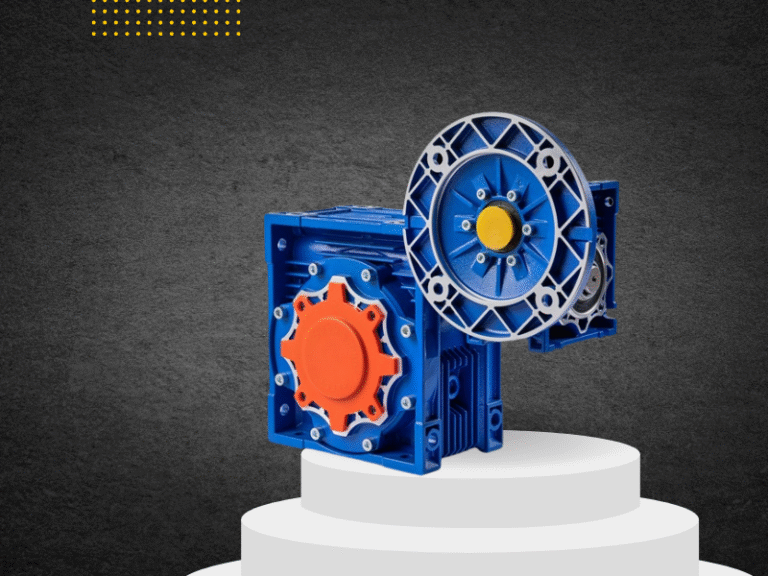
- Helical and bevel gear units
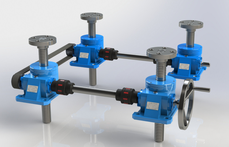
- Screw jacks and electric cylinders
- Custom mechanical transmission systems
- OEM/ODM gearbox solutions
We offer:
- Engineering-driven selection support
- Custom torque, flange, and shaft options
- Robust high-strength shaft designs
- Full testing and quality assurance
- Long-term reliability improvement guidance
If you want to reduce shaft breakage, improve equipment durability, and optimize motion performance, NUODUN can support your project wit.