whatsapp:+86 13622680352

What Is a Gear Reducer and How Does It Work?
If you’ve ever watched a compact motor move a heavy conveyor, lift a platform, or hold a robotic arm perfectly steady, there’s usually a quiet hero in the drive train: the gear reducer.
Industrial motors are great at spinning fast and efficiently—but many real-world loads need the opposite: controlled speed, high torque, and stable motion. That’s exactly where a gear reducer comes in. By using gears to trade speed for torque, a reducer helps a relatively small motor deliver the strength and control required to move “big loads” reliably.
In this article, we’ll break down what a gear reducer is, how it works, the main components inside, common reducer types, and what to consider when selecting one for your application. The goal is simple: give you a clear, practical understanding you can apply immediately—whether you’re building a conveyor line, automating a factory cell, or designing a machine for OEM production.
Why Understanding Gear Reducers Matters
In industrial equipment, performance problems often show up as “the motor isn’t strong enough,” “the motion is jerky,” “the gearbox runs hot,” or “the line speed is unstable.” Many of these issues aren’t caused by the motor itself—but by a mismatch between motor characteristics and the load.
A gear reducer helps bridge that gap by:
- Delivering usable torque at the output shaft
- Reducing speed to a safe, controllable range
- Improving system efficiency by keeping the motor operating in its preferred speed band
- Enhancing reliability by reducing mechanical stress and overheating risks
In short: a reducer translates motor power into motion your machine can actually use.
What Is a Gear Reducer?
A gear reducer is a mechanical device that uses meshing gears to reduce rotational speed while increasing torque at the output. You’ll also hear it called a speed reducer or a type of gearbox (the terms are often used interchangeably in industry).
Where It Sits in a Drive System
In most machines, the gear reducer is installed between the motor and the load, such as:
- Motor → Gear reducer → Conveyor roller
- Servo motor → Planetary reducer → Robot joint
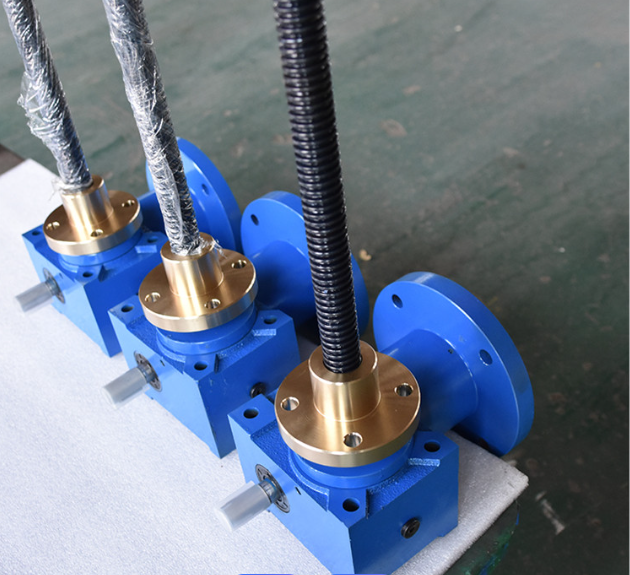
- Motor → Worm reducer → Lifting screw system
Its job is to match the motor’s high-speed rotation to what the application actually requires—often slower, stronger, and more controlled.
The Core Functions of a Gear Reducer
1) Reduce Speed
Many electric motors run efficiently at high RPM. But equipment like conveyors, mixers, indexing tables, and lifting mechanisms usually need much lower speed. A reducer brings the motor speed down to a range that is stable, safe, and process-friendly.
2) Increase Torque
Torque is what turns resistance into movement—accelerating a load, holding position, or overcoming friction. Under the principle of energy conservation, reducing speed allows torque to rise (accounting for losses).
This torque increase is the reason a compact motor can drive heavy loads when paired with the right reducer.
3) Improve Efficiency and Extend Service Life
When a drive system is properly matched, the motor runs closer to its efficient operating region, and the drivetrain experiences less stress. This can improve:
- Motor temperature behavior
- Bearing and gear life
- Overall uptime and maintenance intervals
How Does a Gear Reducer Work? The Basic Principle
A gear reducer works through gear ratios. The simplest way to visualize it is a small gear driving a larger gear:
- The small gear (pinion) spins faster
- The larger gear turns more slowly
- The output torque increases because the larger gear provides mechanical advantage
Understanding Gear Ratio (Speed Reduction Ratio)
The gear ratio is typically determined by the ratio of gear teeth counts (or pitch diameters). For example:
- Input gear: 20 teeth
- Output gear: 80 teeth
- Ratio = 80 / 20 = 4:1
This means:
- Output speed ≈ input speed ÷ 4
- Output torque ≈ input torque × 4 (theoretical, before losses)
A Simple Example: 4:1 Ratio
If your motor is running at 1400 rpm and you use a 4:1 reducer:
- Output speed ≈ 350 rpm
- Output torque (ideal) ≈ 4× motor torque
In reality, friction and lubrication losses reduce the torque slightly, which is why efficiency matters when comparing reducer types.
Multi-Stage Gear Reduction
To achieve larger ratios without extremely large gears, gearboxes often use multiple stages. When stages are in series, total ratio is the product of each stage:
- Stage 1: 4:1
- Stage 2: 5:1
- Total ratio: 20:1
Multi-stage designs allow compact gearboxes to deliver high reduction and high torque—very common in industrial gearmotors and planetary gearboxes.
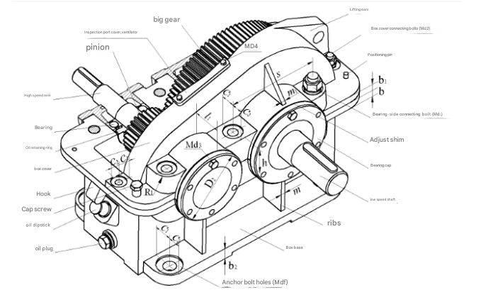
Main Components of a Gear Reducer
A gearbox is more than just gears. Each component supports reliability, load capacity, and long service life.
Input Shaft and Output Shaft
- Input shaft connects to the motor (direct coupling, adapter, or flange)
- Output shaft connects to the load (keyed shaft, hollow shaft, flange, splines, etc.)
These shafts transfer torque while handling radial/axial loads.
Gear Train (Gear Set)
The gear train determines reduction ratio, efficiency, noise behavior, and load capacity. Common gear forms include:
- Spur gears (straight teeth; simple but can be noisier at speed)
- Helical gears (angled teeth; smoother and quieter; widely used in industry)
- Bevel gears (transfer power between intersecting axes)
- Worm gears (high ratios; may provide self-locking under certain conditions)
Bearings and Lubrication System
Bearings support the rotating shafts and manage loads. Lubrication reduces friction and wear and helps remove heat. Depending on gearbox design, lubrication may involve:
- Splash lubrication
- Grease lubrication
- Forced lubrication (for heavy-duty/high-speed systems)
Housing and Seals
The housing provides structural alignment and protects internal components. Seals prevent lubricant leakage and keep contamination out—especially important in dusty environments, washdown areas, or food/pharma facilities.
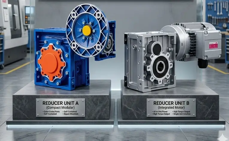
Common Types of Gear Reducers
Different reducer types exist because industrial applications vary widely—speed, torque, precision, space constraints, cleanliness requirements, and budget all matter. Below are the most common categories.
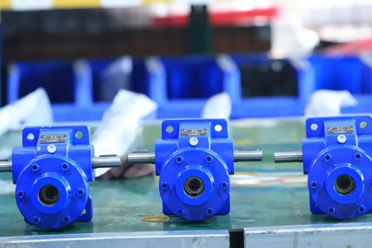
Parallel Shaft Gear Reducers
These have input and output shafts that run parallel. They typically use spur or helical gears.
Where they fit best:
- Conveyors and material handling
- Packaging machinery
- General industrial transmission
Why they’re popular:
- Efficient, robust, and cost-effective
- Broad range of torque and ratios
- Easy integration with standard motors
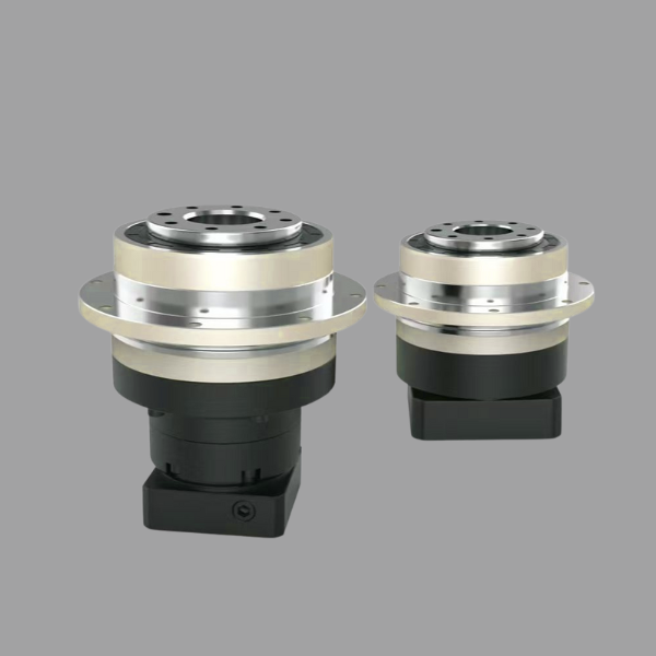
Planetary Gear Reducers
Planetary reducers use a central sun gear, multiple planet gears, and an internal ring gear. They offer high power density and compact size.
Where they fit best:
- Servo systems and automation
- Robots and motion control axes
- Precision positioning equipment
Key advantages:
- High torque in a compact body
- Low backlash options for precision
- Excellent rigidity and dynamic response
Worm Gear Reducers
Worm reducers use a worm (screw-like gear) driving a worm wheel. They can achieve high ratios in a compact design and may offer self-locking in some setups.
Where they fit best:
- Lifting mechanisms and hoists
- Conveyors requiring backdriving prevention
- Space-constrained equipment needing high reduction
Important note:
Worm gear efficiency can be lower than helical/planetary designs, especially at higher ratios—so heat and duty cycle should be considered.
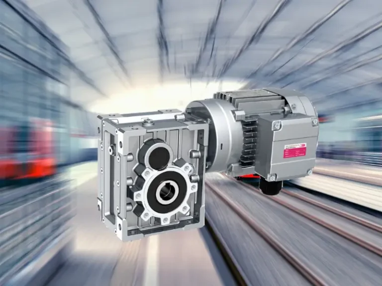
What Gear Reducers Do in Real Applications
Conveyors and Packaging Lines
Reducing speed helps maintain stable line speed, smooth acceleration, and consistent throughput. Proper torque ensures the system can handle product load variation without stalling.
Robots and Automation Equipment
Reducers provide torque amplification and control stability. In robotic joints, the right reducer improves stiffness, positioning accuracy, and repeatability—especially important for pick-and-place, assembly, or CNC automation.
Pumps, Fans, and Mixers
These applications often need a specific process RPM. A reducer matches motor speed to the ideal operating point, lowering energy waste and reducing mechanical stress.
Key Factors to Consider When Choosing a Gear Reducer
This section sets you up for deeper selection work (and leads naturally into the next article).
Required Ratio and Output Torque
Start with the target output speed and load torque. Don’t forget:
- Starting torque (often higher than running torque)
- Overload and shock conditions
- Duty cycle (continuous vs intermittent)
Installation and Interfaces
Consider:
- Mounting type (foot, flange, shaft-mounted)
- Space constraints
- Motor adapter standards
- Output connection style (solid/hollow shaft, keyway, flange)
Efficiency, Noise, Maintenance, and Lifetime Cost
A reducer isn’t only a purchase price decision. In many factories, lifecycle cost matters more:
- Higher efficiency can reduce energy bills and heat
- Lower noise improves operator comfort and compliance
- Longer service intervals reduce downtime and labor costs
FAQ: Gear Reducers (Common Questions)
1) What’s the difference between a gear reducer and a gearbox?
In many industries, they’re used interchangeably. “Gear reducer” emphasizes speed reduction and torque increase, while “gearbox” is a broader term for gear-driven power transmission.
2) Does a higher reduction ratio always mean higher torque?
In theory, torque increases with ratio, but real output torque depends on gearbox efficiency, heat limits, and mechanical strength. Very high ratios can introduce more losses.
3) How do I calculate output speed from a reducer?
Output speed ≈ Motor speed ÷ Reduction ratio.
Example: 1500 rpm motor with 10:1 reducer → ~150 rpm output.
4) How do I estimate output torque?
Output torque ≈ Motor torque × Ratio × Efficiency.
Efficiency varies by gearbox type and design, so use manufacturer data when sizing.
5) What is backlash, and why does it matter?
Backlash is the small clearance between gear teeth. For conveyors it may not matter much, but for robotics, CNC axes, and precise positioning, low backlash improves accuracy and repeatability.
6) Which reducer is best for robots: planetary or helical?
Planetary reducers are commonly used for robots due to compact size, high torque density, and low-backlash options. Helical reducers can still be suitable depending on layout and precision requirements.
7) Are worm gear reducers self-locking?
Some worm gear designs can resist backdriving, but self-locking depends on the lead angle, friction, load, and lubrication. For safety-critical holding, use proper brakes or locking mechanisms where required.
8) What information should I provide for reducer selection?
At minimum: required output speed, torque, duty cycle, shock/overload conditions, mounting orientation, space limits, and motor details (power, speed, frame size). The more complete the data, the safer and more cost-effective the selection.
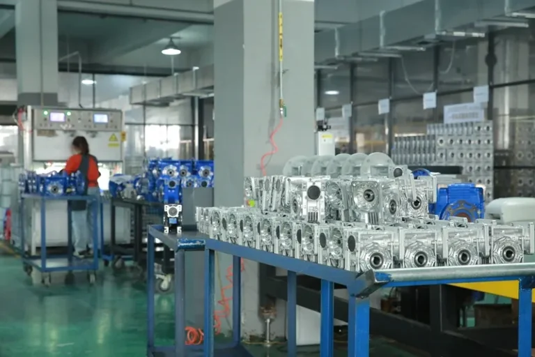
Get Reducer Selection Support from NUODUN (OEM Available)
NUODUN is a transmission equipment manufacturer supporting industrial customers with reliable gear reducer solutions and OEM customization. If you have application parameters such as required torque, speed, ratio, mounting style, and duty cycle, our technical team can help recommend a configuration that fits your system and budget.
You May Also Be Interested In:
Gearbox Maintenance and Lubrication Guide
Gearbox Oil Leakage: Causes, Prevention, and Fast Repair Methods
How to Solve Common Gearbox & Motor Problems
Why Gearbox Shaft Breakage Happens: Causes, Engineering Solutions