whatsapp:+86 13622680352

Screw Jack Selection Guide
Selecting a screw jack (mechanical screw lifting jack) is not just about choosing a tonnage rating . A reliable system depends on how well the jack matches the real operating conditions: axial load direction, stroke, speed, duty cycle, stability limits, and the guiding structure around the spindle. When those factors are understood early, installation becomes simpler, service life improves, and unexpected failures—like vibration, overheating, or spindle buckling—are far less likely.
This guide provides a fixed, engineering-friendly step-by-step method you can reuse on every project. It is written for machine builders, automation engineers, plant maintenance teams, and procurement professionals who need clear selection logic that translates into robust designs and predictable performance.
NUODUN is a professional manufacturer focused on drive systems, power transmission, and linear motion actuator components. If you need application-specific support, NUODUN engineering teams can help you validate sizing, configuration, and accessory choices for your lifting or positioning project.
Why a Step-by-Step Method Matters
Screw jacks are used in lifting platforms, machine leveling, press adjustment, gate lifting, conveyor height change, stage systems, and synchronized multi-jack lifting. The same product series can behave very differently depending on the installation:
- A long spindle under compression may be limited by buckling rather than rated load.
- A horizontal layout without proper guides can create side loads that wear the nut quickly.
- High duty cycles can overheat gearboxes and reduce lubricant life.
- High spindle speeds can trigger vibration if critical speed limits are exceeded.
A fixed selection workflow prevents the most common mistakes: oversizing where it is unnecessary, undersizing where it is risky, and mismatching the jack type to the required accuracy, efficiency, or self-locking behavior.
Key Data to Define Before Selection
A strong selection starts with a complete operating profile. Collect the following data before comparing models.
Load
Define the maximum lifting or compression load (kN, ton, or kg). Then clarify how the load behaves:
- Is one jack carrying the full load, or is the load shared across 2, 4, or more synchronized jacks?
- Is the load static, or does it include impact or shock (light, medium, severe)?
- Is the load centered, or will there be eccentric loading and bending moments due to structure constraints?
Practical note: Many early failures come from side loads or off-center loads that were never accounted for in the axial load calculation.
Stroke
Define stroke using two values:
- Useful stroke (effective travel)
- Reserve margin (safety clearance and installation allowances)
Also specify motion direction and layout:
- Vertical lifting (up/down)
- Horizontal push/pull
- Any angular or swiveling motion in linkages (hinges, tilting platforms)
Speed and Duty Cycle
Speed is usually defined as linear travel speed (mm/s or mm/min). Duty cycle defines how long and how often the jack operates.
Capture:
- Required travel speed
- Cycles per hour (or per day)
- On-time vs rest-time (ED% or equivalent)
- Continuous operation duration (minutes/hours)
High frequency or long continuous operation typically drives the selection toward higher efficiency and better thermal performance.
Accuracy and Positioning Requirements
Define whether the application needs:
- Precise positioning or repeatable location
- Synchronization accuracy for multi-jack systems (example: ±0.1 mm or ±0.5 mm)
- Self-locking or “power-off position holding” without brake
Self-locking needs should be stated clearly at the start because they often determine screw type and motor/brake design.
Environment and Mounting Constraints
Define:
- Temperature range
- Dust, water spray, washdown, corrosion exposure
- Indoor or outdoor operation
- Space limits around the spindle and guides
- Mounting orientation (upright, inverted, horizontal)
Environmental factors strongly influence lubrication choice, protection covers, and corrosion-resistance options.
Step-by-Step: Calculate the Design Load per Jack
Rated capacity in the catalog must be compared to a design load that reflects safety factors and load sharing realities.
Adjusted Load Using a Safety Factor
Start by applying a safety factor to the maximum load:
Ws = W × Sf
Where:
- W = actual maximum load
- Sf = safety factor
Common selection ranges:
- Light shock: Sf ≈ 1.3–1.5
- Medium to heavy shock: Sf ≈ 2.0 or higher
If impact severity is unknown, treat it conservatively. Oversight here is costly because shock loads accelerate thread wear, overload gear teeth, and reduce service life.
Load per Jack in Synchronized Systems
For multi-jack lifting, load distribution is rarely perfectly equal. Use a distribution factor (fd) to account for uneven sharing:
Load per jack = (Ws / number of jacks) × fd
Typical fd references:
- 2 jacks: around 0.95
- 4 jacks: around 0.85
- 5–8 jacks: around 0.80
Selection rule:
- The jack’s rated load must be greater than or equal to the calculated load per jack, with additional margin for real-world alignment and installation tolerances.
Choose the Screw Type
The screw type defines efficiency, speed capability, heat generation, and whether the system naturally resists back-driving.
Machine Screw Jack (Trapezoidal / Acme Screw)
Strengths:
- Simple structure and strong shock tolerance
- Good self-locking tendency in many practical conditions
- Lower cost, robust for heavy industrial adjustment
Best fit:
- Low speed or medium-low frequency
- Heavy loads
- Applications that benefit from self-locking / power-off holding
(equipment leveling, mold height adjustment, platform lifting, machine alignment)
Key note: self-locking behavior depends on lead angle, friction, lubrication, and load direction. Even with machine screws, safety mechanisms (limit switches, mechanical stops, safety nuts) are recommended where risk is high.
Ball Screw Jack
Strengths:
- Higher mechanical efficiency (lower input torque for the same load)
- Higher speed capability, reduced heat generation
- Better potential for repeatable positioning and servo control
Best fit:
- Medium/high speed
- Frequent reciprocating motion
- High positioning accuracy requirements
- Servo-driven automation lines
Key note: ball screw systems are typically not self-locking. If power-off holding is required, plan a brake or an additional holding device.
Quick decision:
- Self-locking + low speed heavy load → Machine screw
- High efficiency + higher speed + servo accuracy → Ball screw
Confirm Speed, RPM, Critical Speed, and Buckling
This section is the difference between “it works in a test” and “it runs reliably for years.”
Estimate Input RPM
From required linear speed V and screw lead (pitch):
Spindle speed N = V / lead
Then include gearbox ratio:
Input speed ≈ (V / lead) × gear ratio
Practical guideline:
- Keep input RPM within a reasonable band for the selected jack and gearbox type to manage heat and wear. Many industrial designs aim to keep input speed in a typical range such as ≤ 1500–1750 rpm, but always confirm the allowable limits for the specific model.
Check Critical Speed
A long rotating spindle can vibrate (whip) as it approaches critical speed. A common stability rule is:
n_op ≤ 0.8 × n_crit
Where:
- n_op = operating spindle speed
- n_crit = critical speed threshold
If operating speed is too close to critical:
- reduce spindle speed (increase lead or change ratio carefully)
- increase spindle diameter
- reduce unsupported length
- add intermediate supports
- reconsider configuration (especially for long horizontal rotating spindle designs)
Check Stability Under Compression (Buckling)
For compression-loaded spindles with high slenderness ratio, do a stability check using Euler/Tetmajer (depending on range and standards used in your design practice). A practical safety factor guidance is:
- Buckling safety factor typically 3–6
(higher when guiding, end conditions, or eccentric loading are uncertain)
If stability is insufficient:
- increase spindle diameter
- shorten unsupported free length
- strengthen guides (make the guide system carry lateral loads)
- improve end restraint
- reconfigure the layout to shift load direction toward tension where feasible
Duty Cycle and Thermal Balance
Heat rise is a predictable outcome of friction and gearbox losses over time. Ignoring duty cycle is one of the most common selection mistakes.
What Drives Temperature Rise
- high duty cycle ED%
- high input RPM
- high load and low efficiency screw/gear combination
- insufficient lubrication or incorrect lubricant selection
- high ambient temperatures or poor heat dissipation in enclosure designs
Practical Duty Cycle Guidance
A commonly used reference in industrial practice:
- Standard mechanical jacks at rated loading often target ED ≤ 20–30% for typical designs.
If duty cycle is higher:
- increase frame size (more thermal mass and capacity)
- select a higher efficiency ball screw option
- improve lubrication strategy (automatic lubrication where needed)
- consider thermal mitigation in the machine design (ventilation, separation from heat sources)
Configuration and Accessories
Once the load, stroke, speed, and stability checks are satisfied, define the configuration and accessory package that ensures safe, maintainable operation.
Structural Configuration Choices
- Translating screw (moving spindle)
- Rotating screw / travelling nut concept (depending on design)
- Vertical upright / inverted / horizontal installation
- Single input shaft / double input shaft
- Direct motor flange connection
Your configuration should minimize side loads, simplify guiding, and allow service access for lubrication and inspection.
Input and Drive Options
- Single input shaft
- Dual input shaft (for flexible transmission layouts)
- Motor direct coupling
- Flange-mounted motor interface
Spindle End Forms
Select the interface that matches your structure:
- flat end
- external threaded end
- flange end
- clevis end (common for pinned joints and articulated motion)
Common Accessories
- Limit switches (travel control and protection)
- Protective bellows/boots/covers (contamination control)
- Position sensors (feedback for automation and synchronization)
- Lubrication devices (manual or automatic)
- Safety nuts (secondary load path / wear monitoring)
- Mechanical stops (fail-safe end-of-travel protection)
Quick Selection Checklist
This checklist can be printed and used as a standard internal template.
Load
- Maximum load W confirmed
- Impact level defined (light/medium/severe)
- Safety factor Sf applied → Ws calculated
- Number of synchronized jacks confirmed
- Distribution factor fd applied → load per jack calculated
- Rated capacity ≥ calculated load per jack with margin
Stroke
- Effective stroke confirmed
- Reserve margin confirmed
- Vertical/horizontal layout confirmed
- Compression vs tension loading confirmed
Speed and Stability
- Required linear speed V confirmed
- Input RPM estimated
- Operating spindle speed verified against critical speed: n_op ≤ 0.8·n_crit
- Compression stability verified (Euler/Tetmajer), safety factor 3–6 applied where appropriate
Duty Cycle and Thermal
- Duty cycle ED% or cycles/hour confirmed
- Thermal risk evaluated for load and speed
- Upsize / higher-efficiency option considered if ED% is high
Configuration and Integration
- Translating screw vs travelling nut concept defined
- Mounting orientation defined
- Spindle end form selected
- Input method selected (single/dual shaft, motor flange)
- Accessory list confirmed: limits, covers, sensors, safety nut, lubrication, stops
Common Application Notes
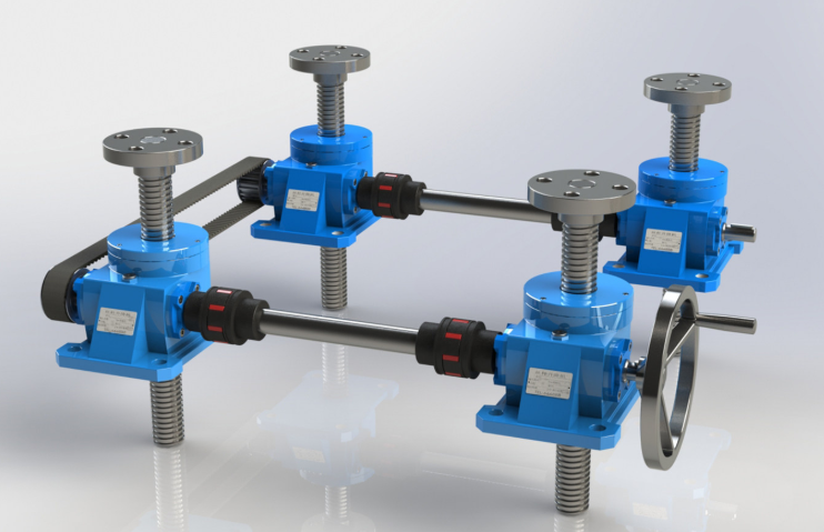
- For synchronized lifting (2, 4, or more jacks), system stiffness and guiding quality matter as much as jack capacity. Load distribution is rarely perfect; that is why fd is used.
- For long strokes under compression, buckling risk can dominate selection. This is often the deciding factor between “works short-term” and “stable long-term.”
- For high-frequency automation, efficiency and heat management become primary. Ball screw designs and proper braking strategy typically perform better in these scenarios.
Frequently Asked Questions
What parameters are most often missing in screw jack inquiries?
Duty cycle, shock level, and the guiding structure are the most commonly underestimated inputs. These strongly influence heat rise and service life.
How do I choose between machine screw and ball screw if I need both accuracy and holding?
If power-off holding is mandatory, machine screw is often preferred. If you need high speed/high duty and servo precision, ball screw is usually better—but plan a brake or holding mechanism.
Is catalog tonnage enough to select a jack?
Not by itself. You must calculate Ws with safety factor and then compute load per jack for multi-jack systems using fd. You also must verify critical speed and buckling for long spindles in compression.
When is buckling most likely to become the limiting factor?
Compression loading with long stroke, limited guides, and any eccentric loading. If the spindle is slender or the free length is long, stability checks are mandatory.
What accessories are most recommended for industrial reliability?
Limit switches, protective covers, lubrication devices, and safety nuts are the most commonly specified. Position feedback is recommended for automation and synchronization control.
If you provide your basic operating data, NUODUN can deliver a selection recommendation and configuration proposal aligned with your real duty conditions.
Send:
- Maximum load (kN/ton/kg), number of jacks, shock level
- Stroke and installation orientation (vertical/horizontal, tension/compression)
- Target speed (mm/s or mm/min) and duty cycle ED% / cycles
- Positioning and synchronization requirements (if any)
- Environment and protection requirements (dust/water/corrosion)
NUODUN, as a professional manufacturer dedicated to drive systems, power transmission, and linear motion actuator components, supports OEM and industrial projects with practical sizing guidance, configuration options, and accessory recommendations to improve stability, uptime, and lifecycle value.